


Custom Designs and Engineering
with more than 20 publications in Dubus Magazine and other print media on antenna related topics like Boom Correction, stacking and plotting I have shown my capacities on this field. For this I make extensive use of EZNEC and 4nec2 simulation tools, a self programmed Yagi Element Configuration Tool and more. Using adequate Analysers like TR 1300 by Planar - OZBOR or Agilent 8594 E in house and sharpening my skills in regular exchange with others professionals at TGN Technology Ltd. or WiMo I am well trained to meet your demands for Research and Development for top range gear on VHF/UHF bands.
What I can do for you is producing full antenna simulation analysis, antenna designs to your specification, assisting in setting up your pilot antenna design with boom correction factors and CAD drawings for production.
References please?
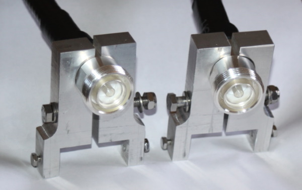
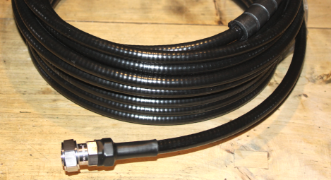
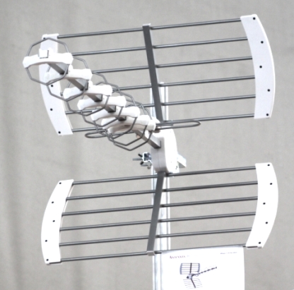
DIN 7/16 cable bushing bracket for 40 x 40 mm boom & confectioning:

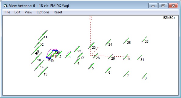
Antennas: My NEC Model
My NEC Model

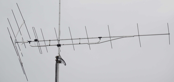
| Freq. | Gain | F/B | |
| 88 MHz | 10.0 dBi | 26 dB | |
| 94 MHz | 10.9 dBi | 36 dB | |
| 102 MHz | 12.2 dBi | 36 dB | |
| 108 MHz | 11.1 dBi | 29 dB |
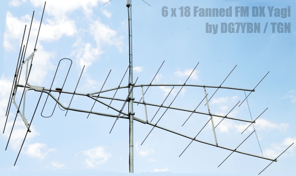
| Freq. | Gain | F/B | |
| 88 MHz | 11.1 dBi | 26 dB | |
| 90 MHz | 11.4 dBi | 28 dB | |
| 94 MHz | 11.9 dBi | > 40 dB | |
| 98 MHz | 12.4 dBi | 32 dB | |
| 102 MHz | 12.7 dBi | 27 dB | |
| 108 MHz | 11.9 dBi | 27 dB |
| Freq. | Gain | F/B | |
| 88 MHz | 10.0 dBi | 26 dB | |
| 90 MHz | 10.3 dBi | 31 dB | |
| 94 MHz | 10.7 dBi | 37 dB | |
| 98 MHz | 11.1 dBi | 28 dB | |
| 102 MHz | 11.3 dBi | 26 dB | |
| 108 MHz | 10.0 dBi | 25 dB |

Boom 2.08 m, Gain ~ 4 ... 8 dBi (45 ... 82 MHz)
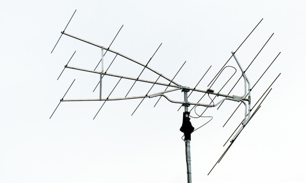
Simulation of antennas and adaption to interlaced combination.
| Freq. | Gain | F/B | |
| 28.2 MHz | 11.3 dBi | 23.8 dB | |
| 28.5 MHz | 11.4 dBi | 23.8 dB | |
| 50.2 MHz | 13.0 dBi | >35 dB |
• TGN Technology - DVB-T Yagi Range Design, Boom Correction and RF Compliant Realisation of Mechanical Design
• WiMo - VHF/UHF Yagis by YU7EF: Boom Correction, Balun Design and Building Details (production ran out)
• Various Publications in Dubus, Practical Wireless and other magazines on Antenna G/T, designs and correction factors for building